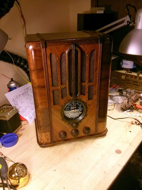
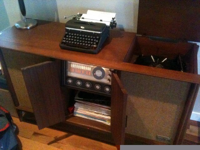
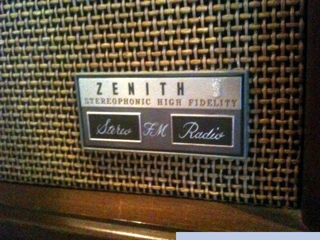
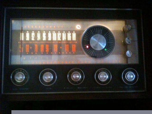
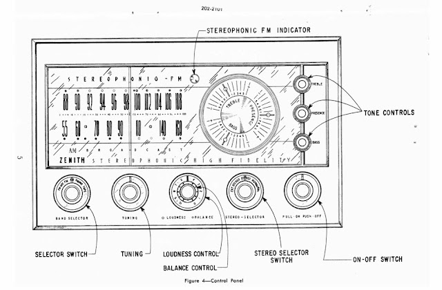
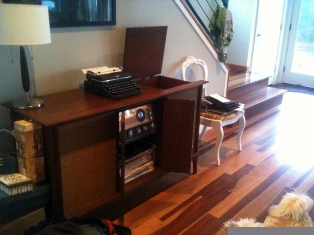
I recently got to work on something a little bit different – a tube hi-fi stereo console! This particular one, a 1962 Zenith MK2670, was a very high-end unit back in its day. It’s a dual-chassis unit with 19 tubes total, using the 12K25 stereophonic FM tuner and 7K31 stereo amplifier chassis with EL84 outputs. All housed in a beautiful mid-century modern cabinet with built-in stereo speakers featuring 12″ woofers and mid- and high-end compression drivers and horns.
![]()
![]()
With 19 total tubes, this model features hi-fi integrated speakers with high-efficiency 12″ woofers and mid and tweeter horns, push-pull EL84 output tubes for each channel, and built-in FM Stereo Multiplex decoding for true stereo hi-fi reproduction.
![]()
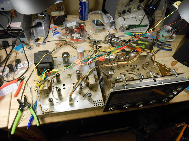
This hi-fi’s owner reported it was working well for several years but started to go downhill shortly before she got in touch to have it fixed. It was taking longer and longer to warm up and sounding more and more distorted, no longer delivering the rich warm sound of a classic hi-fi console. It was good she got in touch – waiting any longer could have led to catastrophic consequences such as component failure or even a fire. I visited her home to test the tubes and pull the chassis, then it was back to my shop for repairs. And what a job it was!
![]()
![]()
![]()
![]()
![]()
This unit had been serviced a couple of times in its life – there were some ’70s era film capacitors installed, and some of the output tubes had been replaced. Most of the tubes were original Zenith fittings and tested strong, though, so very little needed to be replaced. Since it came into the shop in working condition, too, it made the diagnostic process much easier!
![]()
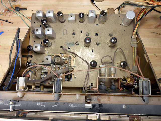
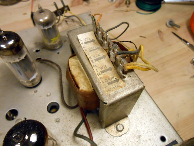
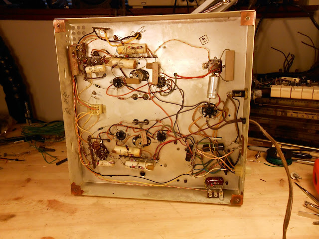
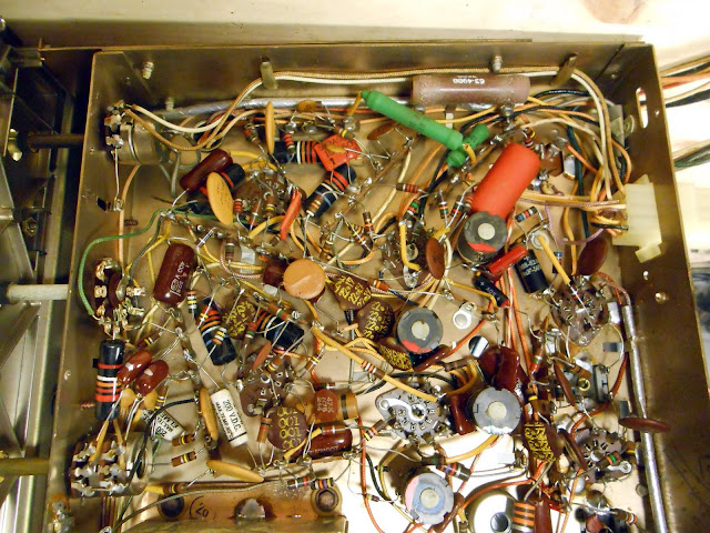
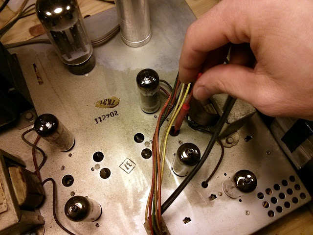
The amplifier circuit is a bit different than most I’ve seen. The negative phase of the output transformers was connected to chassis, and there were two positive phased taps each connected to half of the speakers. It’s an odd arrangement, certainly, which would have let Zenith use woofers of different impedance then the mid/tweeter network without an expensive and complicated impedance matching network. Underneath, though, it’s pretty easy to work on:
![]()
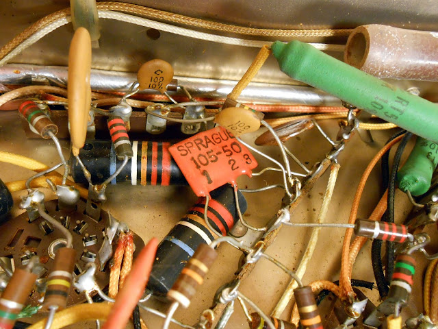
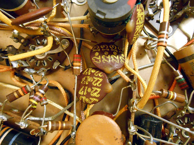
Right away there’s some visible damage. This molded ceramic capacitor blew a piece of the ceramic clean off from overheating. It’s unlikely it was doing much of its job at this point. Despite a nice ceramic body and epoxy sealed ends, it’s still an acid-paper/foil capacitor inside subject to failure, and fail it did.
![]()
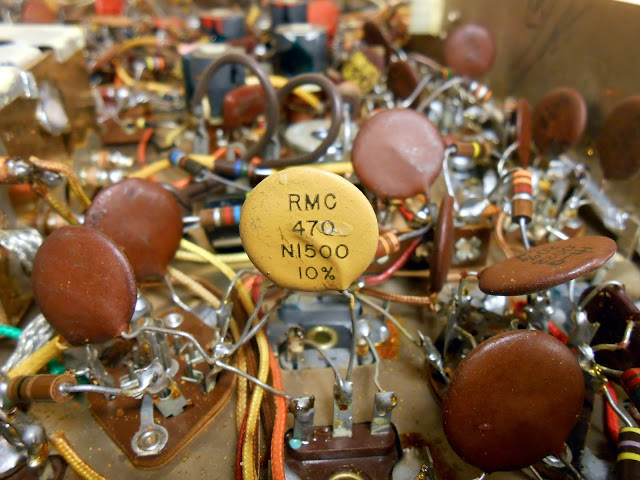
Many of these early disc capacitors were failing as well.
![]()
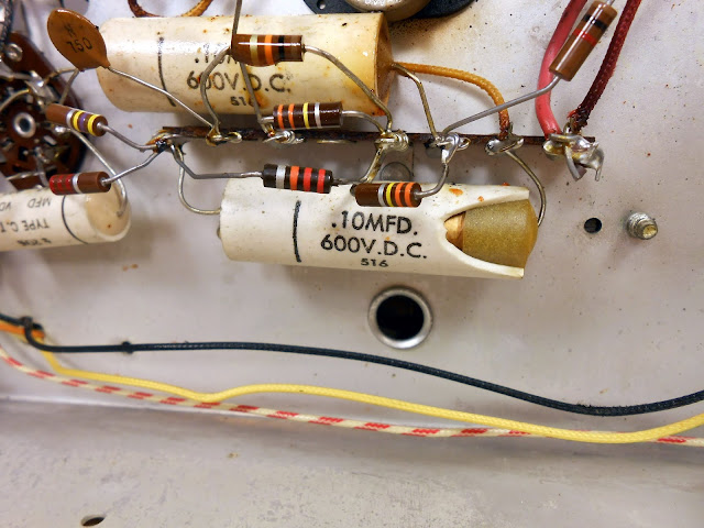
I tested and replaced resistors as necessary, and capacitors. Here’s an in-progress shot showing partial replacement complete. Even the resistors I did remove were very close to spec – Zenith clearly used high quality resistors in this hi-fi. All were shiny with intact bodies and paint, and none had the woody, chalky appearance of a tired carbon resistor.
![]()
![]()
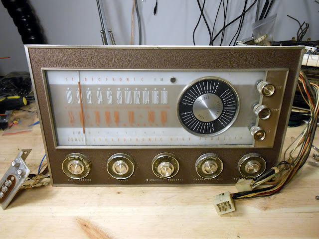
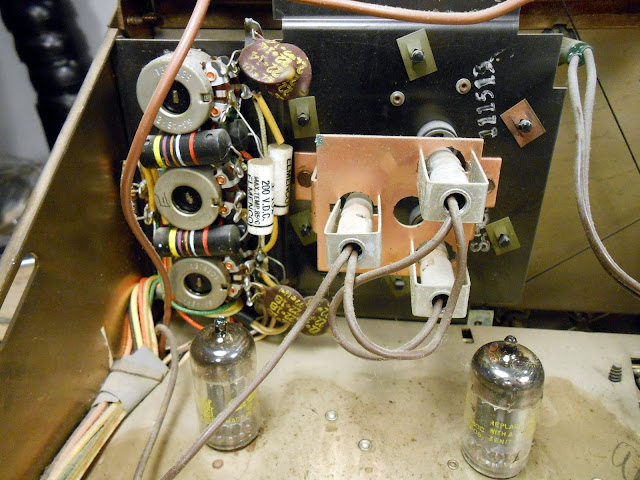
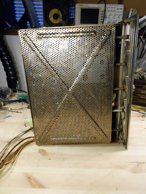
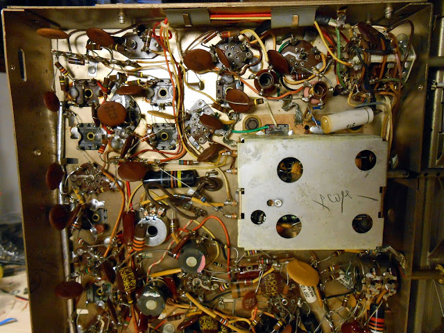
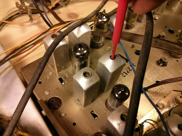
With the amplifier chassis sorted, it was time to move onto the tuner. It’s nicely shielded on the bottom.
![]()
![]()
And there’s a lot going on inside.
![]()
![]()
![]()
![]()
![]()
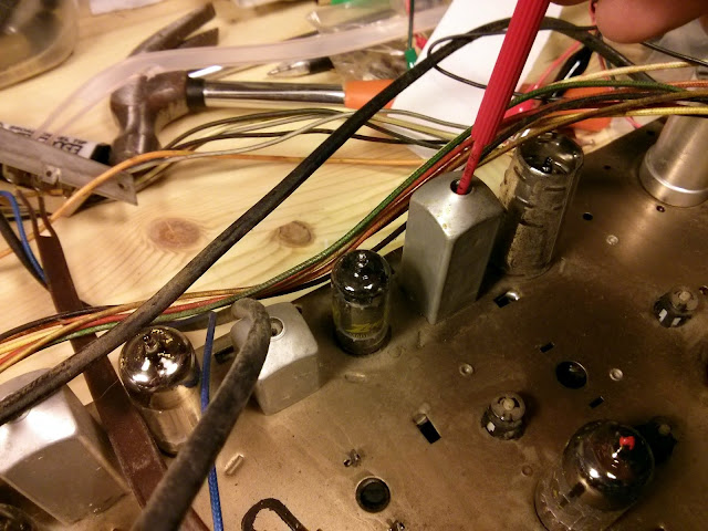
This radio was build very, very densely and in layers. It’s also a modern hi-fi instrument sensitive to wiring changes, so I had to work without disturbing most of the arrangements. Fortunately, Zenith specified high quality carbon film resistors and they were overwhelmingly within tolerance, so it was just a straightforward capacitor replacement.
![]()
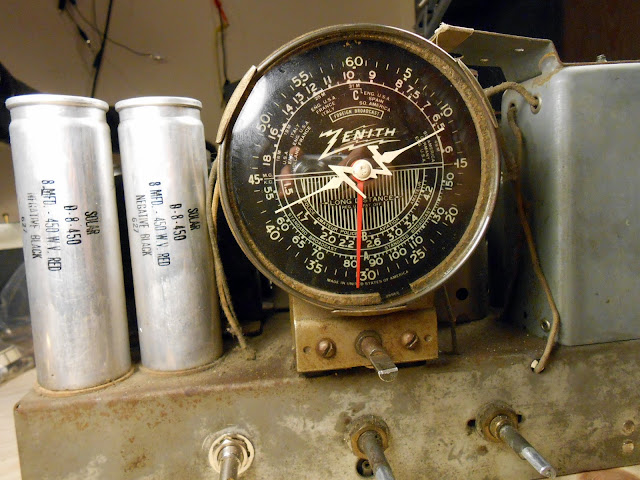
Even film capacitors are much different these days. The ’70s 0.47uF 400V capacitor, top, was replaced with a 0.47 uF 630V capacitor about 1/4 the size. Working with a needle-nose pliers in each hand, I was able to thread capacitors into the proper location under component networks without disturbing the top layer.
![]()
![]()
![]()
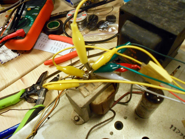
Now it was time for a power-up test. This particular radio uses an odd multi-tapped output transformer arrangement with drivers hooked up to both taps in the cabinet, so I ended up hooking up 4 distinct speakers for testing.
![]()
![]()
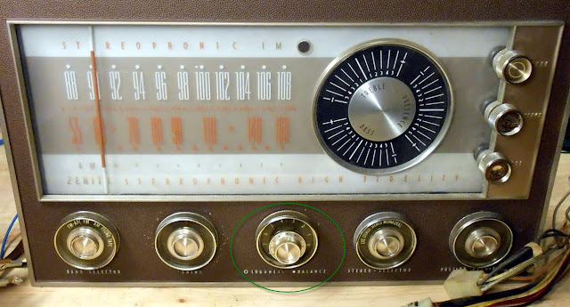
It fired right up and sounded great! There were a few minor issues to resolve, though. For one, there was a bad volume-invariant hum on the AM band only. This was due to a small short which was corrected. The volume controls were behaving pretty erratically, though, which took some investigation.
![]()
![]()
![]()
The unexpected behavior turned out to be due to a control scheme I hadn’t run into before. The “balance” control isn’t an actual fader; instead, the volume controls for the left and right channel are ganged together with a friction clutch. Turning the outer ring turns both together – but turning the inner ring adjusts the friction clutch allowing one to be turned independently to achieve the left-right effect. At the new set point, then, the outer ring will turn both volume controls together to adjust the loudness equally after the fade is applied. It wasn’t a popular control scheme, being replaced after a couple of years, because many consumers found it to be annoying and counter-intuitive.
After understanding how it worked, however, it turns out that it wasn’t gummed up, it was actually working properly. So, on to the next steps! Adjusting the bias on the channels:
![]()
RF and IF Alignment:
![]()
![]()
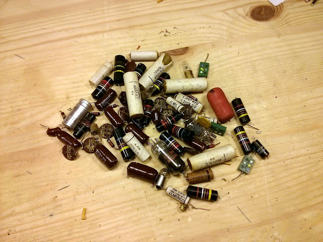
Lots of parts came out of this one!
![]()
This radio is going to continue to serve faithfully for many years, pumping out a warm and rich hi-fi sound and be a beautiful family heirloom to pass on. They just don’t build them like they used to!
![]()
If you need your antique radio repaired, I can help.
![]()
![]()